Installation plans
Example installation plans can be downloaded from this page.
Example circuit diagrams
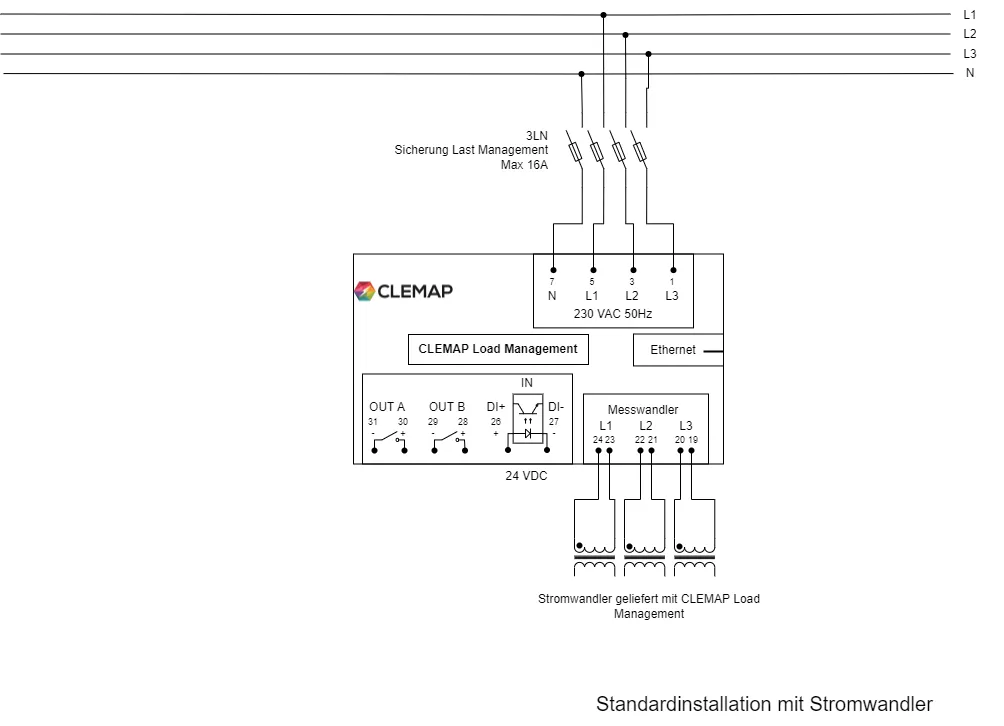
Example of three-phase circuit diagrams with connection instructions:
- Standard installation with current sensors (transformers or Rogowski sensors)
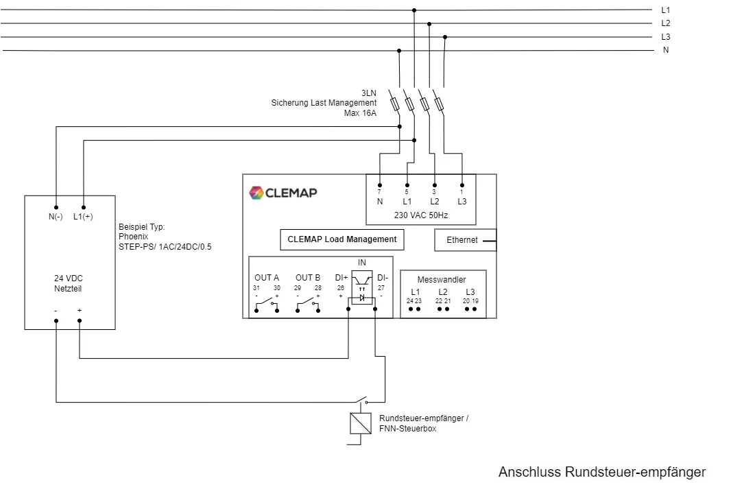
- Connection to the ripple control receiver or FNN control box
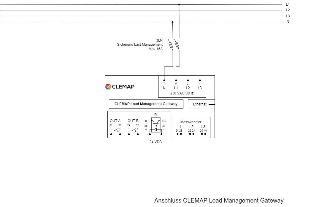
- Electrical installation of a CLEMAP Load Management Gateway
Standard installation
- Basic diagram for installations
- It is ensured that the power at the main connection never exceeds a certain limit value (e.g. 80A).
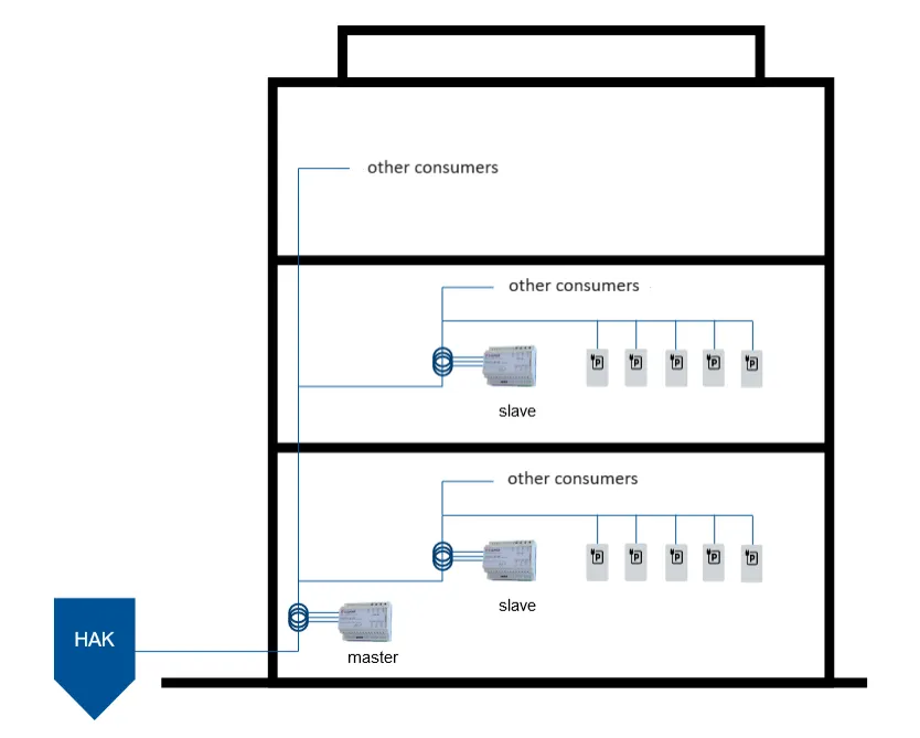
Apartment block with charging stations under household meter
- Apartment block with shared underground parking.
- Each individual charging station is connected to the corresponding household meter.
- It is ensured that the total power at the main connection never exceeds a certain limit value, for example 80A.
Apartment block with monitoring of each individual household meter
- Apartment block with shared underground parking.
- Each individual charging station is connected to the corresponding household meter.
- It is ensured that the total power at the main connection never exceeds a certain limit value, for example 80A.
- It is as well ensured that the power at each houshold meter never exceeds a certain limit value (e.g. 25A).
Installation with multiple circuits
- Charging stations are distributed among different circuits.
- Each circuit contains only charging stations. And there are, for example, a total of 25 charging stations, of which 10 charging stations are mounted on one line and are fused with 63A and the remaining 15 charging stations are mounted on a second line and are fused with 80A.
- It is ensured that the power at the building's main connection never exceeds a certain limit value (e.g. 200A).
Cascading of CLEMAP Load Management
- A main CLEMAP Load Management controls subordinate CLEMAP Load Managements.
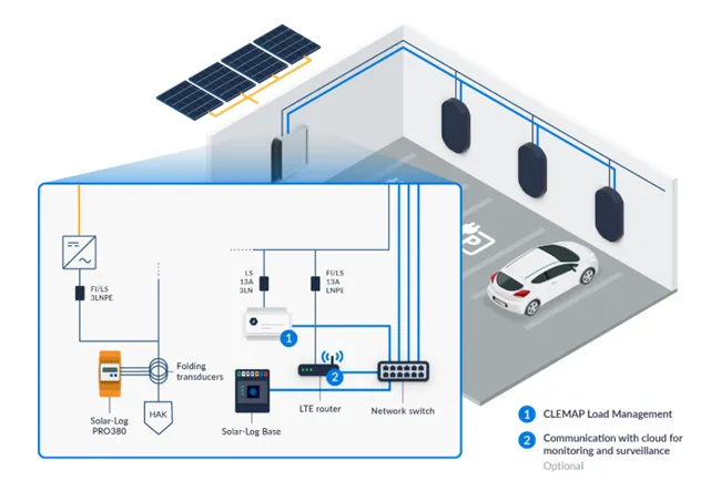
Installation with photovoltaic system monitoring via SolarLog
The CLEMAP Load Management Gateway can interface with a Solar-Log Base paired with a Solar-Log PRO380. In this configuration, the CLEMAP load management system retrieves measurement data directly from the Solar-Log via the Modbus TCP protocol for both the main distribution panel (HAK) and the photovoltaic system. In this setup, the CLEMAP product does not perform direct measurements but instead obtains the data from the Solar-Log.
Dynamic vs. static circuit
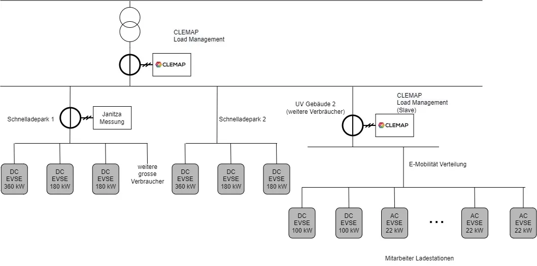
- The CLEMAP Load Management primary unit monitors the main connection using its own measurement.
- The CLEMAP Load Management secondary unit controls the employee charging stations based on its own measurement values and the available power communicated by the primary unit at the transformer level.
- The fast-charging stations in Fast-Charging Park 1 are directly controlled by the primary CLEMAP Load Management unit. Since there are additional consumers in Fast-Charging Park 1, an extra measurement is performed using Janitza to ensure dynamic monitoring of the electrical circuit in Fast-Charging Park 1.
- There are no additional consumers in Fast-Charging Park 2, so static load management is sufficient for Fast-Charging Park 2.
Several transformers
- Parallel connection of transformers (two or more transformers)
- The primary CLEMAP Load Management unit aggregates its own measurements with data from the Janitza measurement device and monitors the load of each transformer individually.
- The secondary CLEMAP Load Management unit controls the employee charging stations based on its own measurement values and the power available at the transformer, as communicated by the primary unit.
- The fast-charging stations in the recharging park are directly controlled by the primary CLEMAP Load Management unit.